What is 3uTools? How to install and use 3uTools in detail

3uTools supports users to manage utility applications more than the traditional way. Easy-to-use interface, will bring interesting experiences to you.
If you are wondering which component of the motherboard needs the most attention, there are certainly many, but one of them called VRM will be the one we need to pay attention to because VRM focuses on helping for stable power of CPU and GPU. So what is VRM and how does it work? Let's learn about this article with WebTech360 .
The VRM (Voltage Regulator Module) circuit is the voltage regulator in the motherboard. With the presence of VRM, the CPU and GPU will be provided with clean power to operate stably.
The VRM circuit is capable of converting DC power to a lower value. For example, the VRM can convert +12VDC or +5VDC power to +1.3VDC or 1.1VDC so that CPU and RAM can work properly. This voltage level is also kept at different limit, they are also known as “DC to DC converter”.
The conversion of voltages into different levels is not a new technology. However, it plays a very important role to ensure the normal operation of electrical and electronic systems.
When the VRM circuit is poor, it will affect the performance of the processor when it loads tasks. More seriously, the computer system can be turned off suddenly, especially when OC. Therefore, users need to pay more attention to this part to help the computer work well.
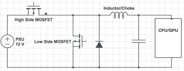
A modern computer power supply (PSU) typically supplies 12V to the motherboard. However, CPUs and GPUs cannot withstand that voltage. At that time, the VRM will work its magic when adjusting the source to about 1.3V, 1.1V or lower so that the GPU/CPU works in the best state.
The VRM circuit must work correctly to avoid unfortunate incidents, especially those affecting the CPU. This explains why its structure is much more complicated than that of conventional transformers.
Basically, a VRM circuit is a buck converter - a type of device that can drop exactly the desired voltage level. The structure of the circuit consists of 3 main parts which are:
- MOSFET: Metal-Oxide Semiconductor Field-Effect Transistor.
- Inductor
- Capacitor
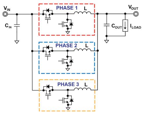
In addition, they are also integrated with control ICs (also known as PWM controllers). There are two common types of VRM circuits: single-phase and multi-phase. In particular, most computers today are equipped with multiphase circuits with the following schematic diagram:
The phases of the VRM circuit will take turns supplying power to the CPU for short and staggered intervals. Therefore, at a time, only 1 phase is active, but the total power generated for the supply remains stable. This is an important factor for the computer to work well and promote the performance of the CPU/GPU.
Using a multiphase VRM circuitry also brings a pretty big benefit in terms of heat dissipation. The transmission of power over a larger area reduces local heat generation. This reduces pressure on system components, improving power and operating costs.

VRM Single Phase

Multi-Phase VRM
Multiphase VRM circuits are sold with the symbol “ 6+2” or “8+3” . The number before the plus sign is the number of phases dedicated to providing power to the CPU. The other number indicates the number of phases to supply voltage to other components of the motherboard such as RAM.
In case the first number is greater than 8, namely “12 + 1” or “18 + 1” , the actual number of phases is not so large. The manufacturer will use a voltage doubler (doubler) with the operating method is to split the power between the two lanes of MOSFET, capacitor and inductor available in each phase.
Thanks to the doublers, the manufacturer will take advantage of the benefits of the current phase without having to install additional physical phases, thus saving a lot of costs. However, mirrored phases will not be quite as efficient as real ones. The frequency of the supply current will be halved and there will be a certain delay. Moreover, at a time, only 1 of 2 phases can be turned on. Therefore, the way to create a VRM circuit with multiple phases using a doubler is just a way of marketing sales of the manufacturers, not bringing too much effect in reality.
Example: A VRM with 6 phases mirrored (to 12 phases) will typically perform less efficiently than a real 7 or 8 phase VRM.
With a basic VRM, it was possible to ensure the power source for the mid-range CPU to operate in a state. But when you need to overclock or perform performance-intensive tasks, then the quality of the VRM circuit will become more important.
The reason is because with 2 power supplies of the same power level, the one with VRM can give you a higher maximum power level of each line. As a result, power-intensive tasks will be quickly responded to by the VRM circuit. Users also do not have to invest in a larger power supply to meet the operation of the machine.
Hope this article helped you visualize the importance of VRM as well as answer questions related to this important component. Wish you will choose a quality motherboard as well as know which is a good motherboard to build a quality computer set at the best price!
3uTools supports users to manage utility applications more than the traditional way. Easy-to-use interface, will bring interesting experiences to you.
Rendering is the process of creating an image from a model into a movie scene or image using computer software.
The CPU is the data processing center, or simply understood, it is the brain that controls most of the rest of the components in a computer.
The GPU is the processor that handles graphics-related tasks for the CPU's central processor. Features on GPUs go far beyond basic graphics drivers like Intel's GPU
Flyer is a form of advertising, a marketing product that has existed for a long time, also known as leaflets, product marketing brochures.
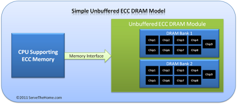
ECC RAM is a type of RAM that has the ability to control the flow of data accessed in it to help automatically correct errors. ECC RAM has very high stability which helps you to reduce risk.
Ray Tracing is a technique that helps a computer create an image by tracing the path of light through pixels on the same image plane.
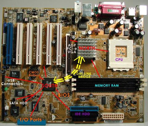
Chipset is a collection of chips, chipset refers to the chip on the mainboard or on the expansion card. On PC, commonly known as northbridge and southbridge.
Hyper threading is a hyper-threading technology and is known as Intel HT technology by globally famous technology manufacturer Intel.
On the quality screen, they integrate a technology called V-Sync, FreeSync. Let WebTech360 explain to you about V-Sync, what is FreeSync?
Anti-aliasing is the main adjustment mode to help objects and people become softer and not angular, the game experience will also be better.
Animation is an age-old method in which people make motions of images based on still images.
Footage is unedited raw footage and footage. You can understand that footage is all the components that make up a video, and footage is very diverse.
Storyboard is a storyboard, consisting of a series of illustrations and accompanied by notes about what is going on, carrying the content of the story.
Struggling with Microsoft Teams Mac Error Keychain Issues? Discover proven, step-by-step fixes to resolve Keychain errors on Mac, restore smooth login, and boost productivity fast. No tech expertise needed!
Tired of Microsoft Teams crashing with "Hard Error"? This 2026 guide delivers step-by-step fixes for seamless video calls and chats. Clear cache, update, reinstall—solve it now!
Tired of Microsoft Teams crashing due to msvcp140.dll missing errors? Discover proven, step-by-step fixes to restore smooth video calls and chats. Works on Windows 10/11 with latest updates.
Tired of Microsoft Teams Meeting ID not working? Get instant fixes for join errors on desktop, mobile, or web. Step-by-step troubleshooting with latest updates to rejoin meetings seamlessly. No tech skills needed!
Struggling with Microsoft Teams "Welcome Error" startup loop? Discover step-by-step fixes to resolve the issue quickly. Clear cache, reset app, and more for seamless Teams experience. Updated with latest solutions.
Stuck with Microsoft Teams "Disabled Error" Account Blocked? Discover proven, step-by-step solutions to fix the issue fast, regain access, and prevent future blocks. No tech skills needed!
Master how to use Microsoft Teams Copilot for AI-powered meetings. Step-by-step guide with latest tips to generate recaps, answer questions, and boost productivity effortlessly. Transform your Teams experience today!
Master Microsoft Teams Breakout Rooms with this beginner-friendly tutorial. Step-by-step guide to creating, managing, and optimizing breakout rooms for dynamic 2026 meetings and workshops. Boost engagement now!
Stuck with Microsoft Teams Recording Save Error? Get instant, step-by-step fixes for saving recordings effortlessly. Proven solutions for all common issues – no tech skills needed!
Discover how to create a Wiki page in Microsoft Teams effortlessly. This ultimate guide covers step-by-step instructions, tips, and best practices to boost your team's knowledge sharing and productivity. Perfect for beginners!
Stuck on Microsoft Teams "Error S" screen? Discover proven, step-by-step solutions to fix Microsoft Teams Error S fast. Clear cache, restart, update & more for seamless teamwork. Works on latest versions!
Struggling with Microsoft Teams proxy error on Windows 10? Discover step-by-step fixes to resolve proxy authentication issues, connection failures, and more. Get Teams running smoothly in minutes with our expert guide.
Tired of Microsoft Teams Town Hall Event Error ruining your events? Get step-by-step fixes for scheduling, access, and registration issues. Restore seamless virtual town halls today with our ultimate guide.
Discover the simplest way to download Microsoft Teams for Mac, MacBook Air, and MacBook Pro. Step-by-step instructions, system requirements, and troubleshooting tips for seamless installation in the latest version. Get started now!
Stuck with Microsoft Teams Web Login Error? Get instant fixes for common issues like "Something went wrong" or login loops. Step-by-step guide to resolve Teams web login problems and stay productive. Updated with latest browser tweaks.


